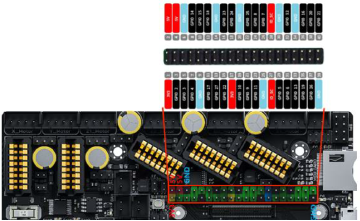
When i received the BIGTREETECH E3EZ* together with a CB1* i was wondering how the pinout / gpio on the board was setup. Unfortunately the picture in the User-Manual of the E3EZ was relatively blurry.
GPIO stands for General-Purpose Input/Output. It refers to the pins on a microcontroller or single-board computer, like the Raspberry Pi, that can be programmed to serve as either inputs or outputs. These pins enable the device to interact with the external world by receiving or transmitting digital signals. Through software programming, developers can configure GPIO pins to read data from sensors (inputs) or send signals to actuators (outputs), facilitating versatile applications like the control of fans, lights or other 3D printing accessories.
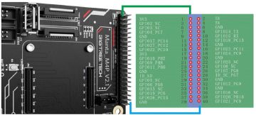
Thankfully the pinout is the same on the Manta M4P which is why i was able to extract the data from there (page 9):
BIGTREETECH describes the pinout of the CM4 the same as the one of the Raspberry pi. However when being used with the CB1, the Pinout Changes. I extracted that information and then used various sources of research to find the corresponding GPIO port: This is the final result:
| Pin | CM4 | CB1 | Comment |
|---|---|---|---|
| 1 | 3.3V | 3.3V | Pin is the same on both boards |
| 2 | 5V | 5V | Pin is the same on both boards |
| 3 | GPIO2 | Not connected | Not connected on the CB1 |
| 4 | 5V | 5V | Pin is the same on both boards |
| 5 | GPIO3 | Not connected | Not connected on the CB1 |
| 6 | GND | GND | Pin is the same on both boards |
| 7 | GPIO4 | PC7 / GPIO71 | Different GPIO numbering |
| 8 | GPIO14 | TX | Incompatible - different function! |
| 9 | GND | GND | Pin is the same on both boards |
| 10 | GPIO15 | RX | Incompatible - different function! |
| 11 | GPIO17 | PC14 / GPIO78 | Different GPIO numbering |
| 12 | GPIO18 | PC13 / GPIO77 | Different GPIO numbering |
| 13 | GPIO27 | PC12 / GPIO76 | Different GPIO numbering |
| 14 | GND | GND | Pin is the same on both boards |
| 15 | GPIO22 | PC10 / GPIO74 | Different GPIO numbering |
| 16 | GPIO23 | PC11 / GPIO75 | Different GPIO numbering |
| 17 | 3.3V | 3.3V | Pin is the same on both boards |
| 18 | GPIO24 | PC9 / GPIO73 | Different GPIO numbering |
| 19 | GPIO10 | PH7 / GPIO231 | Different GPIO numbering |
| 20 | GND | GND | Pin is the same on both boards |
| 21 | GPIO9 | PH8 / GPIO232 | Different GPIO numbering |
| 22 | GPIO25 | Not connected | Not connected on the CB1 |
| 23 | GPIO11 | ph6 / GPIO230 | Different GPIO numbering |
| 24 | GPIO8 | Not connected | Not connected on the CB1 |
| 25 | GND | GND | Pin is the same on both boards |
| 26 | GPIO7 | PG8 / GPIO200 | Different GPIO numbering |
| 27 | ID_SD | ID_SD | Pin is the same on both boards |
| 28 | ID_SC | PG7 / GPIO199 | Incompatible - different function! |
| 29 | GPIO5 | Not connected | Not connected on the CB1 |
| 30 | GND | GND | Pin is the same on both boards |
| 31 | GPIO6 | PG6 / GPIO198 | Different GPIO numbering |
| 32 | GPIO12 | PG9 / GPIO201 | Different GPIO numbering |
| 33 | GPIO13 | Not connected | Not connected on the CB1 |
| 34 | GND | GND | Pin is the same on both boards |
| 35 | GPIO19 | PC6 / GPIO70 | Different GPIO numbering |
| 36 | GPIO16 | Not connected | Not connected on the CB1 |
| 37 | GPIO26 | PC15 / GPIO79 | Different GPIO numbering |
| 38 | GPIO20 | PH10 / GPIO234 | Different GPIO numbering |
| 39 | GND | GND | Pin is the same on both boards |
| 40 | GPIO21 | PC8 / GPIO72 | Different GPIO numbering |
Update: Now i finally found a mapping in the CB1 repo - check there if you want to see the mapping for the BTT PI or CB1 MMC version.

